Monday, November 14, 2016

Resistor Shunt kawat tembaga 1,2mm

Aplikasi resistor shunt cukup banyak. Efisiensi sekarangan menjadi kewajiban bagi stiap alat. Dituntut memiliki effisiensi yang tinggi. Sama halnya dengan resistor shunt. Saya dapat referensi dari microchip.
Mengukur input PV dan output charger dengan resistor shunt 5miliOhm.

Perhitungan sbb:
Shunt 0,005 Ohm
pada saat arus masuk sebesar 10A maka;
V=ixR
V=10 x 0,005
V=0,05Volt.
Berhubung input PV lebih rendah dari Ground, maka nilainya negatif.(-0,05Volt).
Maka digunakan inverting Amplifier(OP-Amp).

Gain  = -100.
Vgain = Vread x Gain
Vgain = -0,05 x -100
Vgain = 5Volt.

Jadi nilai 5 volt bisa dibaca Adc (Analog to digital converter) atau sebagai sensor arus pada mikrokontroler.
Shunt bisa dibuat dengan menghitung resistansi kabel/kawat. 5miliOhm setara kawat tembaga annealing (yang digulung tidak terlalu susah/agak lunak) dengan diameter 1,2mm dengan panjang 350mm atau 35cm. Anda bisa buat sendiri.

Sedangkan shunt satu sisi yang lain nilai yang diperoleh positif/ lebih tinggi dari ground, maka menggunakan non inverting amplifier.

Pemanfaatan Saturation Mosfet

Mosfet memiliki karakteristik semikonduktor. Semakin tinggi Rds on maka arus yang keluar akan semakin kecil. Selama ini sifat saturation mosfet jarang dipakai. Rata-rata designer hanya mencari nilai optimum Rds on, tegangan capacitance dan thermal. Kali ini saya akan memakai mosfet IRF 9540. Mosfet type P.Chanel. Sifatnya yaitu apabila tegangan gate dibawah positif 5 volt atau -5 maka mosfet akan on. Sedangkan bila gate diberi tegangan sama dengan sumber(source), maka mosfet akan mati(totally turn off). Tegangan saturation mosfet digunakan untuk mensuply LED atau 7805 yang sifatnya linear. Semakin tinggi perbedaan tegangan maka akan semakin banyak panas yang terbuang. Saturation mosfet type tsb adalah -2 sampai -4 Volt .Dengan resistor 47k dari gate ke sumber (+), dan resistor 47k series 3 (=141k), maka tegangan dari gate ke sumber = -3,2Volt. Maka mosfet sudah dalam kondisi saturation. Dalam kondisi ini tegangan drain dalam kondisi open circuit diukur = tegangan sumber. Namun apabila diberi load 500 ohm saja, maka tegangan akan drop ke 8-9 Volt. Drop tegangan tidak seperti resistor shunt yang dibuang menjadi panas. Namun seperti sifat dioda atau semikonduktor yang lain, arus ada yang dibuang dan ada yang tertahan. Berhubung Power disipasi mosfet cukup besar maka lebih baik sifatnya daripada resistor yang power disipasinya lebih kecil.
Sifat tersebut bisa dimanfaatkan untuk menurunkan tegangan misalnya dari 60V ke nilai tertentu dengan bantuan DC-DC converter yang lain. Misalnya LM2596,LM2576. Tegangan maksimum dari converter tersebut maksimal 40V, Absolut 45V. Akan tepat jika 60V dipasangkan dengan mosfet saturation tadi. dengan proteksi Zener 45Volt/42Volt maka converter akan aman. Nah anda sudah bisa membuat power suply dari 60V ke 12V/5V/adjustable. Berhubung sifat dari saturation mosfet hanya bisa untuk ampere kecil sekitar 10-50mA. Maka cocok untuk power suply mikrocontroler. untuk variasi ampere yang besar bisa digunakan mosfet yang besar yang dikendalikan dari mikrocontroler(PWM).

Thursday, August 25, 2016

Data Vmp minimum, Vmp STC dan Voc 100VDC PV

 Merakit Solar Modul/ Solar Panel adalah hal yang lumrah bagi para intsaler system on grid maupun off grid. Hal yang paling diperhatikan yang pertama adalah tegangan maksimum yang mampu diserap oleh system. Entah itu charger PWM, MPPT, ataupun inverter on grid. Parameter yang pertama adalah tegangan maksimum PV atau open cicuit (Voc) maksimum, dan Tegangan minimal yang mampu diserap. Tabel diatas adalah contoh system DC dari solar panel dengan tegangan maksimal VOC 100VDC.
Parameter terpenting yang kedua adalah power rating dari Solar panel. Kalau memakai device yang bagus artinya spesifikasi tertulis mampu dibebani 100%, maka desainer bisa memasukkan power rating PV dikalikan 120%. Kenapa 20% lebih tinggi dari device?. Ini untuk kasus instaler di Indonesia. Suhu rata2 di indonesia lebih tinggi dibandingkan negara eropa, jepang dan amerika. Meskipun radiasi levelnya lebih dari 1000W/meter persegi. Namun yang mampu diserap hanya 1000. Akan tetapi suhu cell menjadi panas dan hal itu dapat menurunkan output power pada solar panel. Untuk menghitungnya bisa melakukan pengukuran suhu aktual pada cell dikalikan dengan dengan coefisien suhu pada datasheet produk.
Hal tersebut yang paling mempengaruhi output power pada solar modul. Aktualnya kenapa power maksimal yang kita peroleh dari system hanya sekitar 75%-80% dari rating solar modul yang diinstal. Untuk menaikkan power efficiency bisa menggunakan backsheet aluminium, Artinya proses pendinginan cell lebih cepat. Cara extrem yang lain bisa menambah pendingin pada sisi belakang solar panel. Cara instant yang biasa diaplikasikan adalah dengan memilih device yang mempunyai effisiensi tinggi, Namun konsekuensinya cost akan lebih tinggi.

Wednesday, August 24, 2016

MPPT 12V 10A Ditest memakai 100WP 36Cell (MPPT-20-150WP)

1. Memperoleh tenaga atau daya yang dihasilkan Solar panel bisa menggunakan sensor arus, sensor radiasi ditambahkan dengan sensor suhu. Namun ada cara lagi yang paling murah yaitu dengan menghitung duty cyclenya terlebih dahulu dengan melihat datasheet produk. Parameter Radiasi yang digunakan yaitu radiasi 100-1000W/m persegi. Duty cycle bisa langsung diaplikasikan ke mikrokontroler untuk mendrive mosfet/IGBT/FET. Namun tidak seakurat menggunakan sensor arus atau sensor radiasi.
Kelebihannya jika tanpa sensor bisa langsung bekerja tanpa membaca arus dari Solar panel. Dan tingkat akurasi sekitar 90%.
2.Contoh tabel diatas adalah tabel duty cycle untuk membuat charger 12V memakai solar panel 100WP 36Cell mono. Tabel diatas sudah ditest dan bisa berfungsi dengan baik untuk charging battery lithium 12V.

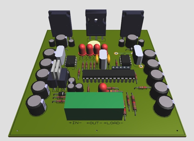
       Dibawah ini hasil dari revisi yang ke-8 untuk PCB-desingnya. sedangkan untuk coding menggunakan arduino uno sudah sangat sering direvisi. Untuk versi open sourcenya akan segera dirilis. Untuk versi produksi masih tahap coding. kisaran harga Rp.280rb. minat call : bambangnur23@gmail.(tokopedia). Kalau yang ingin bereksperimen, terutama Arduino user, Silahkan. Saya sediakan schematic coding, Bill off Material dan Lay Out PCB-nya.


Berikut Bill-Off Materialnya : 
Top Silk Dan Lay Out PCB.
Schematic :


Data spesifikasi :
1. Battery 12V. Low Voltage disconect 11,2. High Voltage disconect 14,6.
2.Self Consumsion 20-30mA.(0.2-0.4Watt).
3.Input voltage range 15-55VDC.
4.Topology low side buck.
5.Floating grounding system.
6.Dutycycle self adaptif (max power point tracking).
7.Mosfet rating 21A. Safe operation at 8-12A.
8.Tested 100WP 36Cell.

Dan Berikut Coding Arduinonya.
//Sensorless Buck Maximum Power Point Tracking 15-25VDC to-12V
//By          : Bambang Nurdiansyah
//Present to  : Bilqis talita Sakhi (My Daughter)
//Last Update : 05 September 2016 (working freq 10-200Khz @ default setting 100Khz)
//For Battery Voltage More than 24V system, please use buck converter 10-80VDC to 9VDC min 300mA and then connect to 78M05/7805 to supply Atmega 8/168/328P


const int pin_Vin = 0;            // pin of Vin connected  to (A0) = read input voltage/PV to ground, see scematic detail. (fix variable)
const int pin_Vid = 1;            // pin of Vid connected to  (A1) = read voltage drop input from ground to negatif PV input, see schematic detail (fix variable)
const int pin_Vout = 2;           // pin of Vout connected to (A2) = read output voltage/battery (fix variable)
const int led_5 = 5;              // pin led 25% Battery to   (D5) = show battery capacyti 25% (fix variable)
const int led_6 = 6;              // pin led 50% Battery to   (D6) = show battery capacyti 50% (fix variable)
const int led_7 = 7;              // pin led 75% Battery to   (D7) = show battery capacyti 75% (fix variable)
const int led_8 = 8;              // pin led 100% Battery to  (D8) = show battery capacyti 100% or Full Charge (fix variable)
const int avgNum = 8;             // Number of iterations of the adc routine to average the adc readings(fix variable).
const int Low_batt = 97;          // battery system low voltage disconect (11V).
const int Vout_max = 124;         // battery system charging at Max (14V).
const int cycletime = 10;         // Default frequency 100Khz with period 10us. this value can change according basic calculation off switching frequency and hardware setting. can swing from 1khz to 200 khz accroding period/ frequency (2-1000us) example 10khz = period 100us,, 20khz = period 50us. so this value is flexible
const int x = 9;                  // pin mosfet low side to   (D9) according hardware configuration. on this setting use low side buck for lower voltage on the N Chanel Mosfet to decrease thermal effect. it mean increase efficiency of system.(fix variable)
const int load_10 = 10;           // pin load control to      (D10) this pin fuction control load on or off when battery voltage low. this pin can use as dimmer load/LED according mosfet power rating.
int Vin = 0;                      // Variable to store Input Voltage, this is RAW unit (0 - 1023 = use voltage devider 220k and 10k = voltage scale 8,89565217391304 (swing from 0 to 115VDC)-this can use up to 126VDC Voc and this value = 5.5VDC maximum voltage suply microcontroler(from datasheet)
int Vid = 0;                      // Variable voltage drop input voltage, according schematic this value usually negatif, so we must multiply -1 to get positif value, or use inverting OP-AMP
int Vout = 0;                     // Variable to store Output Voltage, this is RAW unit (0 - 1023) (swing from 10-70VDC).
int Vin_min = 144;                // Variable to store Vin_min, this is RAW unit (0 - 1023) = min PV voltage = 16VDC. (default setting use 36cell for Vmp).
int Vin_max = 1023;               // Variable to store Vin_min, this is RAW unit (0 - 1023) = max PV voltage = 115VDC. (default setting use 192 cell for Voc).
int switch_state = 0;             // State condition to control main mosfet pin D9.
boolean mppt = false;             // Variable to store state of MPPT.
long i = 0;  // Variable to store iteration
int onTime = 0;  // Variable to store ON time of MOSFET, in microseconds = 10% 40khz maksimum duty cycle for 192cell (PV=Voc) in and 11v out(Battery very low = 11v)
int offTime = 10;  // Variable to store OF time of MOSFET, in microseconds = 90% 40khz maksimum duty cycle for 192cell (PV=Voc) in and 11v out(Battery very low = 11v)
void setup()
{
  //Serial.begin(9600);
  // running with high speed clock (set prescale to 16)
  // so that analog sampling time is now approximately 17microsecond
  // Source: Arduino Cookbook by MichaelMargolis 2nd chapter recipe 18-9
  bitClear(ADCSRA, ADPS0) ;
  bitClear(ADCSRA, ADPS1) ;
  bitSet(ADCSRA, ADPS2) ;
//  Set switchPin to output mode
  pinMode(led_5, OUTPUT); //pin led 25% Battery
  pinMode(led_6, OUTPUT); //pin led 50% Battery
  pinMode(led_7, OUTPUT); //pin led 75% Battery
  pinMode(led_8, OUTPUT); //pin led 100% Battery
  pinMode(x, OUTPUT);     //sets the x as digital PWM output to pin 9 to drive main mosfet
  pinMode(load_10, OUTPUT); //pin led Load control mosfet
  // Source: http://playground.arduino.cc/Code/PwmFrequency
  TCCR2B = TCCR2B & 0b11111000 | 0x01;
}

void determine_Vout_Max_Vin_min(void)  // Tracking Vin min (Vmp PV input 16-120VDC)
{
  Vout = analogRead(pin_Vout);          // Read Output Voltage or Battery Volt.
  Vid = (analogRead(pin_Vid))*(-1);     // Read Voltage Drop input, from ground to negativ PV input, this value usually negatif, can change with code in software or OP-AMP in hardware
  Vin = (analogRead(pin_Vin))+(Vid);    // Read Input Voltage from PV, this value we can get from summing input voltage to ground with votage drop input.

 if ((Vin >= 0) && (Vin <= 202)) // detect 36cell(20WP-160WP) single modul cell5/6 inch mono/poly
  {
    Vin_min = 144;                       // Vmp @ radiation level 100W/m= 16.10VDC
    Vin_max = 202;                       // Vmp @ radiation level 1000W/m= 22.68VDC
}
// ------------------------------------------------------------------------
// This routine reads and averages the analog inputs for this system
//
// It is called with the ADC channel number (pin number) and returns the average ADC
// value as an integer.
//
// Credit: tp://www.timnolan.com/uploads/Arduihtno%20Solar/ppt.pde
// ------------------------------------------------------------------------

int read_adc(int channel)
{
  int sum = 0;
  int temp;
  int i;

  for (i = 0; i < avgNum; i++);
  {//through reading raw adc values avgNum number of times
    temp = analogRead(channel); // read the input pin
    sum += temp;                // store sum for averaging
    delayMicroseconds(10);      // pauses for 10 microseconds
  }
  return (sum / avgNum);        // divide sum by AVG_NUM to get average and return it
}

void loop()
{
  Vout = analogRead(pin_Vout);          // Read Output Voltage or Battery Volt.
  Vid = (analogRead(pin_Vid))*(-1);     // Read Voltage Drop input, from ground to negativ PV input, this value usually negatif, can change with code in software or use inverting  OP-AMP in hardware
  Vin = (analogRead(pin_Vin))+(Vid);    // Read Input Voltage from PV, this value we can get from summing input voltage to ground with votage drop input.

  if ((Vin < Vin_min) || (Vout >= Vout_max))
  {
    mppt = false;
    onTime = 0;
    offTime = 10;
  }
  else if ((Vout < Vout_max) && (Vin >= Vin_min))
  {
    mppt = true;
    onTime = ((Vout / Vin) * cycletime);
    offTime = cycletime - onTime;
  }
  if (onTime >= 1)
  {
    switch_state = 1;
  }
  else if (onTime <= 0)
  {
    switch_state = 0;
  }

  i = 0;

  while ((i < 18) && mppt)
  {

    digitalWrite(x, switch_state);  // sets the x ON/OFF Accoding value onTime
    delayMicroseconds(onTime);// Turn on Mosfet @ Low side
    digitalWrite(x, 0);    // sets the x OFF
    delayMicroseconds(offTime);   // Turn off Mosfet @ Low side
    i = i + 1;

  }


  Vout = analogRead(pin_Vout);          // Read Output Voltage or Battery Volt.
  Vid = (analogRead(pin_Vid))*(-1);     // Read Voltage Drop input, from ground to negativ PV input, this value usually negatif, can change with code in software or OP-AMP in hardware
  Vin = (analogRead(pin_Vin))+(Vid);    // Read Input Voltage from PV, this value we can get from summing input voltage to ground with votage drop input.

  if ((Vin <= Vin_min) || (Vout >= Vout_max))
  {
    mppt = false;
    onTime = 0;
    offTime = 10;
  }
  else if ((Vout < Vout_max) && (Vin >= Vin_min))
  {
    mppt = true;
    onTime = ((Vout / Vin) * cycletime);
    offTime = cycletime - onTime;
  }
  if (onTime >= 1)
  {
    switch_state = 1;
  }
  else if (onTime <= 0)
  {
    switch_state = 0;
  }

  i = 0;

  while ((i < 18) && mppt);
  {
    digitalWrite(x, switch_state);  // sets the x ON
    delayMicroseconds(onTime);// ON time of MOSFET High side & OFF Time Low side
    digitalWrite(x, 0);    // sets the x OFF
    delayMicroseconds(offTime);   // OFF time of MOSFET High side & on Time Low side
    i = i + 1;
  }
  if ((Vout >= 98) && (Vout <= 103)) // 12VDC battery 25%
  {
    digitalWrite(led_5, 1); //led 25%
    digitalWrite(led_6, 0);
    digitalWrite(led_7, 0);
    digitalWrite(led_8, 0);
    delay(1);
  }
  else if ((Vout >= 104) && (Vout <= 109)) // 12VDC battery 50%
  {
    digitalWrite(led_5, 1); //led 25%
    digitalWrite(led_6, 1); //led 50%
    digitalWrite(led_7, 0);
    digitalWrite(led_8, 0);
    delay(1);
  }
  if ((Vout >= 110) && (Vout <= 115)) // 12VDC battery 75%
  {
    digitalWrite(led_5, 1); //led 25%
    digitalWrite(led_6, 1); //led 50%
    digitalWrite(led_7, 1); //led 75%
    digitalWrite(led_8, 0);
    delay(1);
  }
  else if ((Vout >= 116) && (Vout <= 121)) // 12VDC battery 100%
  {
    digitalWrite(led_5, 1); //led 25%
    digitalWrite(led_6, 1); //led 50%
    digitalWrite(led_7, 1); //led 75%
    digitalWrite(led_8, 1); //led 100%
    delay(1);
  }
   Vout = analogRead(pin_Vout);   // Read Output Voltage or battery voltage
   if (Vout > Low_batt)
   {
    digitalWrite(load_10, 1); //turn on load on the condition range voltage battery
    delay(123000);
   }
   else if (Vout <= Low_batt)
   {
    digitalWrite(led_5, 0);
    digitalWrite(led_6, 0);
    digitalWrite(led_7, 0);
    digitalWrite(led_8, 0);
    digitalWrite(load_10, 0); // turn off load when low battery and out off voltage limit.
    delay(123000);
   }
   if (Vout >= Vout_max)
   {
    digitalWrite(led_5, 1); //led 25%
    digitalWrite(led_6, 1); //led 50%
    digitalWrite(led_7, 1); //led 75%
    digitalWrite(led_8, 1); //led 100%0
    digitalWrite(x, 0);
    digitalWrite(load_10, 1);
    delay(123000);
   }
}


Voltage devider for microcontroler (pembagi tegangan untuk mikrokontroler)

 1. Dasar untuk membuat buck converter adalah rangkaian pembagi tegangan.
simulasi dari gambar diatas cukup untuk membuat system pembagi tegangan dari system 12VDC, 24V,48V-60V-100V 150V-250V-500V dan 1000VDC dengan losis sytem 0.5 mA dikalikan tegangan kerja yang diukur.
 2.Contoh 1000VDC diukur tegangan 900V.
Maka daya yang hilang = 900 x 0.5 x 0.001 = 0.45Watt.
Maka cukup menggunakan resistor metal dengan daya 0.6 atau 0.5 watt.
3.Contoh ke 2 .Pada system 28.5V, diukur tegangan 24V.
maka daya yang hilang = 24 x 0.5 x 0.001 = 0.012Watt.
Maka cukup dengan memilih resistor dengan daya maksimal 0.1 watt (SMD) atau kalau tidak ada cukup dengan resistor metal biasa.

Thursday, June 30, 2016

Wich one best home inverter for your solar system?

1. Outback F3648XR with Trov 2, (Grid Interactive, booth, on grid and off grid + battery backup, Less setting,  disadvantage only efficiency arround 92%).This type will be supperior model if increase the efficiency.
2.SMA Sunny Island. (Supperior efficiency arround 95%, support generator, less faill system, disadvantage not support on grid mode).
3.Scheneider XW+ series.(Off grid/on grid mode with setting, generator support, battery backup, peak efficiency arround 94%, disadvantage long time connect generator, or bad for computer server)

Tuesday, May 31, 2016

Low-Frequency Inverters

Introduction to Low-Frequency Inverters

For those who are unaware, the purpose of an off-grid inverter is simple, yet incredibly important for anyone who is looking to set up an off-grid or back up power system, including solar powered systems. Inverters convert the DC power stored within a battery (direct current, 12V, 24V or 48V) into AC power (alternating current, 230-240V) that can be used to run your household items and electrical appliances, from fridges to televisions to mobile phone chargers. Inverters are an essential item for anyone without access to a mains power source, as they can easily provide a plentiful amount of electricity.
Inverters come in many different shapes and sizes, and vary in a diverse amount of ways. There are two main contrasting characteristics between different types of off-grid inverter:
  1. The type of power output, categorised by which sine wave it uses – modified or pure sine wave (see more details in our article on this subject). Photonic Universe only stocks pure sine wave inverters, which are more efficient and have a broader range of suitable appliances they can power compared to modified sine wave inverters.
  2. What internal frequency the inverter circuits operate at - low frequency or high frequency (not to be confused with AC power output frequency which is a standard 50Hz for our inverters).
We are pleased to add low-frequency inverters to our catalogue, and this article is going to help anyone who is looking to buy an inverter find out whether a low-frequency inverter is right for them, so that they can make an informed and confident purchase.
Low-frequency inverters have the advantage over high-frequency inverters in two fields: peak power capacity, and reliability. Low-frequency inverters are designed to deal with higher power spikes for longer periods of time than high-frequency inverters. Power spikes can occur for a number of reasons (e.g. devices like power tools, pumps, vacuum cleaners and other appliances with electric motors require high starting power); when inverters experience such spikes, they can endure the increased power for a short period of time before shutting down in order to prevent any damage being done to them. Low-frequency inverters have much greater peak power capacity to handle large loads with power spikes than high-frequency inverters. In fact, low-frequency inverters can operate at the peak power level which is up to 300% of their nominal power level for several seconds, while high-frequency inverters can operate at 200% power level for a small fraction of a second. The second main difference is reliability: low-frequency inverters operate using powerful transformers, which are more reliable and sturdy than the high-frequency inverter’s MOSFETs, which use electronic switching and more prone to damage, particularly at high power levels.
In addition to these qualities, low-frequency inverters come with a wide range of technical features and capabilities which most high-frequency inverters lack; these include a built-in battery charger; UPS (Uninterruptible Power Supply) functions; by-pass mode with no battery connected; power saving mode; various charge settings (like different battery types and charging voltages).
In terms of other differences, low frequency inverters are designed for large off-grid power systems and are more suitably equipped for powerful appliances; therefore, they are typically within the high power category of invertor, with their power levels normally within the thousands, typically 2000W-3000W and above (high frequency inverters are also available in lower power categories such as 300W, 600W, 1000W, 1500W etc.) In addition, in most cases low frequency inverters do not include mains power sockets – they come with terminals where AC wires should be connected which then connect to mains sockets.
Low-frequency inverters are not ideal for everyone; they’re very large and are considerably heavier than high-frequency inverters, and would be best suited for those who either are building an off-grid power system with no significant power restrictions, or who run powerful appliances and devices with electric motors like power tools, washing machines, vacuum cleaners and air conditioners. Low-frequency inverters are also best suited for those who want to power various kitchen appliances such as refrigerators, microwaves, dishwashers and ovens.
Enhanced peak performance capacity and improved reliability of low frequency inverters mean that they cost more than high frequency inverters. If you do not consume a lot of energy and you only have small appliances that you need to power, or you have limited space for an inverter, then a high frequency inverter would be more suitable for you.
Low-frequency inverters remain a fantastic investment for anyone who has a lot of powerful electrical appliances in a place with limited or no access to standard electricity. Coupled with a suitable solar power kit, low frequency inverters can not only to provide a reliable backup power solution, but completely replace conventional electricity by the same quality power supply. The price you would pay for a low frequency inverter over a high frequency inverter should be considered a long term investment, given how unlikely the low frequency inverter is to break down. They are indeed bigger, stronger, and tougher.
© Photonic Universe Ltd, 2014