1. Memperoleh tenaga atau daya yang dihasilkan Solar panel bisa menggunakan sensor arus, sensor radiasi ditambahkan dengan sensor suhu. Namun ada cara lagi yang paling murah yaitu dengan menghitung duty cyclenya terlebih dahulu dengan melihat datasheet produk. Parameter Radiasi yang digunakan yaitu radiasi 100-1000W/m persegi. Duty cycle bisa langsung diaplikasikan ke mikrokontroler untuk mendrive mosfet/IGBT/FET. Namun tidak seakurat menggunakan sensor arus atau sensor radiasi.
Kelebihannya jika tanpa sensor bisa langsung bekerja tanpa membaca arus dari Solar panel. Dan tingkat akurasi sekitar 90%.
2.Contoh tabel diatas adalah tabel duty cycle untuk membuat charger 12V memakai solar panel 100WP 36Cell mono. Tabel diatas sudah ditest dan bisa berfungsi dengan baik untuk charging battery lithium 12V.
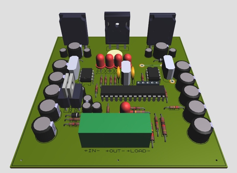
Dibawah ini hasil dari revisi yang ke-8 untuk PCB-desingnya. sedangkan untuk coding menggunakan arduino uno sudah sangat sering direvisi. Untuk versi open sourcenya akan segera dirilis. Untuk versi produksi masih tahap coding. kisaran harga Rp.280rb. minat call : bambangnur23@gmail.(tokopedia). Kalau yang ingin bereksperimen, terutama Arduino user, Silahkan. Saya sediakan schematic coding, Bill off Material dan Lay Out PCB-nya.
Berikut Bill-Off Materialnya :
Top Silk Dan Lay Out PCB.
Schematic :
Data spesifikasi :
1. Battery 12V. Low Voltage disconect 11,2. High Voltage disconect 14,6.
2.Self Consumsion 20-30mA.(0.2-0.4Watt).
3.Input voltage range 15-55VDC.
4.Topology low side buck.
5.Floating grounding system.
6.Dutycycle self adaptif (max power point tracking).
7.Mosfet rating 21A. Safe operation at 8-12A.
8.Tested 100WP 36Cell.
Dan Berikut Coding Arduinonya.
//Sensorless Buck Maximum Power Point Tracking 15-25VDC to-12V
//By : Bambang Nurdiansyah
//Present to : Bilqis talita Sakhi (My Daughter)
//Last Update : 05 September 2016 (working freq 10-200Khz @ default setting 100Khz)
//For Battery Voltage More than 24V system, please use buck converter 10-80VDC to 9VDC min 300mA and then connect to 78M05/7805 to supply Atmega 8/168/328P
const int pin_Vin = 0; // pin of Vin connected to (A0) = read input voltage/PV to ground, see scematic detail. (fix variable)
const int pin_Vid = 1; // pin of Vid connected to (A1) = read voltage drop input from ground to negatif PV input, see schematic detail (fix variable)
const int pin_Vout = 2; // pin of Vout connected to (A2) = read output voltage/battery (fix variable)
const int led_5 = 5; // pin led 25% Battery to (D5) = show battery capacyti 25% (fix variable)
const int led_6 = 6; // pin led 50% Battery to (D6) = show battery capacyti 50% (fix variable)
const int led_7 = 7; // pin led 75% Battery to (D7) = show battery capacyti 75% (fix variable)
const int led_8 = 8; // pin led 100% Battery to (D8) = show battery capacyti 100% or Full Charge (fix variable)
const int avgNum = 8; // Number of iterations of the adc routine to average the adc readings(fix variable).
const int Low_batt = 97; // battery system low voltage disconect (11V).
const int Vout_max = 124; // battery system charging at Max (14V).
const int cycletime = 10; // Default frequency 100Khz with period 10us. this value can change according basic calculation off switching frequency and hardware setting. can swing from 1khz to 200 khz accroding period/ frequency (2-1000us) example 10khz = period 100us,, 20khz = period 50us. so this value is flexible
const int x = 9; // pin mosfet low side to (D9) according hardware configuration. on this setting use low side buck for lower voltage on the N Chanel Mosfet to decrease thermal effect. it mean increase efficiency of system.(fix variable)
const int load_10 = 10; // pin load control to (D10) this pin fuction control load on or off when battery voltage low. this pin can use as dimmer load/LED according mosfet power rating.
int Vin = 0; // Variable to store Input Voltage, this is RAW unit (0 - 1023 = use voltage devider 220k and 10k = voltage scale 8,89565217391304 (swing from 0 to 115VDC)-this can use up to 126VDC Voc and this value = 5.5VDC maximum voltage suply microcontroler(from datasheet)
int Vid = 0; // Variable voltage drop input voltage, according schematic this value usually negatif, so we must multiply -1 to get positif value, or use inverting OP-AMP
int Vout = 0; // Variable to store Output Voltage, this is RAW unit (0 - 1023) (swing from 10-70VDC).
int Vin_min = 144; // Variable to store Vin_min, this is RAW unit (0 - 1023) = min PV voltage = 16VDC. (default setting use 36cell for Vmp).
int Vin_max = 1023; // Variable to store Vin_min, this is RAW unit (0 - 1023) = max PV voltage = 115VDC. (default setting use 192 cell for Voc).
int switch_state = 0; // State condition to control main mosfet pin D9.
boolean mppt = false; // Variable to store state of MPPT.
long i = 0; // Variable to store iteration
int onTime = 0; // Variable to store ON time of MOSFET, in microseconds = 10% 40khz maksimum duty cycle for 192cell (PV=Voc) in and 11v out(Battery very low = 11v)
int offTime = 10; // Variable to store OF time of MOSFET, in microseconds = 90% 40khz maksimum duty cycle for 192cell (PV=Voc) in and 11v out(Battery very low = 11v)
void setup()
{
//Serial.begin(9600);
// running with high speed clock (set prescale to 16)
// so that analog sampling time is now approximately 17microsecond
// Source: Arduino Cookbook by MichaelMargolis 2nd chapter recipe 18-9
bitClear(ADCSRA, ADPS0) ;
bitClear(ADCSRA, ADPS1) ;
bitSet(ADCSRA, ADPS2) ;
// Set switchPin to output mode
pinMode(led_5, OUTPUT); //pin led 25% Battery
pinMode(led_6, OUTPUT); //pin led 50% Battery
pinMode(led_7, OUTPUT); //pin led 75% Battery
pinMode(led_8, OUTPUT); //pin led 100% Battery
pinMode(x, OUTPUT); //sets the x as digital PWM output to pin 9 to drive main mosfet
pinMode(load_10, OUTPUT); //pin led Load control mosfet
// Source: http://playground.arduino.cc/Code/PwmFrequency
TCCR2B = TCCR2B & 0b11111000 | 0x01;
}
void determine_Vout_Max_Vin_min(void) // Tracking Vin min (Vmp PV input 16-120VDC)
{
Vout = analogRead(pin_Vout); // Read Output Voltage or Battery Volt.
Vid = (analogRead(pin_Vid))*(-1); // Read Voltage Drop input, from ground to negativ PV input, this value usually negatif, can change with code in software or OP-AMP in hardware
Vin = (analogRead(pin_Vin))+(Vid); // Read Input Voltage from PV, this value we can get from summing input voltage to ground with votage drop input.
if ((Vin >= 0) && (Vin <= 202)) // detect 36cell(20WP-160WP) single modul cell5/6 inch mono/poly
{
Vin_min = 144; // Vmp @ radiation level 100W/m= 16.10VDC
Vin_max = 202; // Vmp @ radiation level 1000W/m= 22.68VDC
}
// ------------------------------------------------------------------------
// This routine reads and averages the analog inputs for this system
//
// It is called with the ADC channel number (pin number) and returns the average ADC
// value as an integer.
//
// Credit: tp://www.timnolan.com/uploads/Arduihtno%20Solar/ppt.pde
// ------------------------------------------------------------------------
int read_adc(int channel)
{
int sum = 0;
int temp;
int i;
for (i = 0; i < avgNum; i++);
{//through reading raw adc values avgNum number of times
temp = analogRead(channel); // read the input pin
sum += temp; // store sum for averaging
delayMicroseconds(10); // pauses for 10 microseconds
}
return (sum / avgNum); // divide sum by AVG_NUM to get average and return it
}
void loop()
{
Vout = analogRead(pin_Vout); // Read Output Voltage or Battery Volt.
Vid = (analogRead(pin_Vid))*(-1); // Read Voltage Drop input, from ground to negativ PV input, this value usually negatif, can change with code in software or use inverting OP-AMP in hardware
Vin = (analogRead(pin_Vin))+(Vid); // Read Input Voltage from PV, this value we can get from summing input voltage to ground with votage drop input.
if ((Vin < Vin_min) || (Vout >= Vout_max))
{
mppt = false;
onTime = 0;
offTime = 10;
}
else if ((Vout < Vout_max) && (Vin >= Vin_min))
{
mppt = true;
onTime = ((Vout / Vin) * cycletime);
offTime = cycletime - onTime;
}
if (onTime >= 1)
{
switch_state = 1;
}
else if (onTime <= 0)
{
switch_state = 0;
}
i = 0;
while ((i < 18) && mppt)
{
digitalWrite(x, switch_state); // sets the x ON/OFF Accoding value onTime
delayMicroseconds(onTime);// Turn on Mosfet @ Low side
digitalWrite(x, 0); // sets the x OFF
delayMicroseconds(offTime); // Turn off Mosfet @ Low side
i = i + 1;
}
Vout = analogRead(pin_Vout); // Read Output Voltage or Battery Volt.
Vid = (analogRead(pin_Vid))*(-1); // Read Voltage Drop input, from ground to negativ PV input, this value usually negatif, can change with code in software or OP-AMP in hardware
Vin = (analogRead(pin_Vin))+(Vid); // Read Input Voltage from PV, this value we can get from summing input voltage to ground with votage drop input.
if ((Vin <= Vin_min) || (Vout >= Vout_max))
{
mppt = false;
onTime = 0;
offTime = 10;
}
else if ((Vout < Vout_max) && (Vin >= Vin_min))
{
mppt = true;
onTime = ((Vout / Vin) * cycletime);
offTime = cycletime - onTime;
}
if (onTime >= 1)
{
switch_state = 1;
}
else if (onTime <= 0)
{
switch_state = 0;
}
i = 0;
while ((i < 18) && mppt);
{
digitalWrite(x, switch_state); // sets the x ON
delayMicroseconds(onTime);// ON time of MOSFET High side & OFF Time Low side
digitalWrite(x, 0); // sets the x OFF
delayMicroseconds(offTime); // OFF time of MOSFET High side & on Time Low side
i = i + 1;
}
if ((Vout >= 98) && (Vout <= 103)) // 12VDC battery 25%
{
digitalWrite(led_5, 1); //led 25%
digitalWrite(led_6, 0);
digitalWrite(led_7, 0);
digitalWrite(led_8, 0);
delay(1);
}
else if ((Vout >= 104) && (Vout <= 109)) // 12VDC battery 50%
{
digitalWrite(led_5, 1); //led 25%
digitalWrite(led_6, 1); //led 50%
digitalWrite(led_7, 0);
digitalWrite(led_8, 0);
delay(1);
}
if ((Vout >= 110) && (Vout <= 115)) // 12VDC battery 75%
{
digitalWrite(led_5, 1); //led 25%
digitalWrite(led_6, 1); //led 50%
digitalWrite(led_7, 1); //led 75%
digitalWrite(led_8, 0);
delay(1);
}
else if ((Vout >= 116) && (Vout <= 121)) // 12VDC battery 100%
{
digitalWrite(led_5, 1); //led 25%
digitalWrite(led_6, 1); //led 50%
digitalWrite(led_7, 1); //led 75%
digitalWrite(led_8, 1); //led 100%
delay(1);
}
Vout = analogRead(pin_Vout); // Read Output Voltage or battery voltage
if (Vout > Low_batt)
{
digitalWrite(load_10, 1); //turn on load on the condition range voltage battery
delay(123000);
}
else if (Vout <= Low_batt)
{
digitalWrite(led_5, 0);
digitalWrite(led_6, 0);
digitalWrite(led_7, 0);
digitalWrite(led_8, 0);
digitalWrite(load_10, 0); // turn off load when low battery and out off voltage limit.
delay(123000);
}
if (Vout >= Vout_max)
{
digitalWrite(led_5, 1); //led 25%
digitalWrite(led_6, 1); //led 50%
digitalWrite(led_7, 1); //led 75%
digitalWrite(led_8, 1); //led 100%0
digitalWrite(x, 0);
digitalWrite(load_10, 1);
delay(123000);
}
}